I took a break, partly due to high workload at work, partly due to a short trip to my family. I did enjoy it, and even enjoyed driving that tiny, brand new Ford Fiesta I got from Hertz. That was a nice surprise, I paid for Ka, and got Fiesta.
Last two evenings before the departure (well, not exactly, last two evenings were mostly about packing, planning the trip, getting the Google Maps working on my phone etc etc).. what was I talking about? Oh yes. Last two evenings before the departure were about making the RFM12B work with Due. I finally decided on removing the display, and the freed SPI port is now used for RFM12B. I started porting the library to Due, but that turned out to be pretty complex task, as the library uses various bits and pieces specific for AVR (like EEPROM etc.) and I gave up pretty quickly as I had that feeling of reinventing the wheel. I took the library from Boredomprojects and first tests looked really promising, it could talk to Arduino running the latest version of Jeelib.
Happy about the progress, I tried to send a broadcast message to my already existing devices with RFM12B - and... well, nothing happened. After some debugging, I figured out two things that were wrong:
- the existing devices use old version of the library. New version adds one byte in the header for destination or source address
- the new library initializes the RFM12B to a different speed
After fixing those two problems - nothing happened. I tried all I could think of, but the Due running new library with my patches still doesn't talk to the old devices. The packet seems to be correct, the CRC matches, the channel and speed is the same... I gave up for the moment as I had no time to pursue that. I'll debug the init sequence using my good old Saleae clone and see if there are any differences.
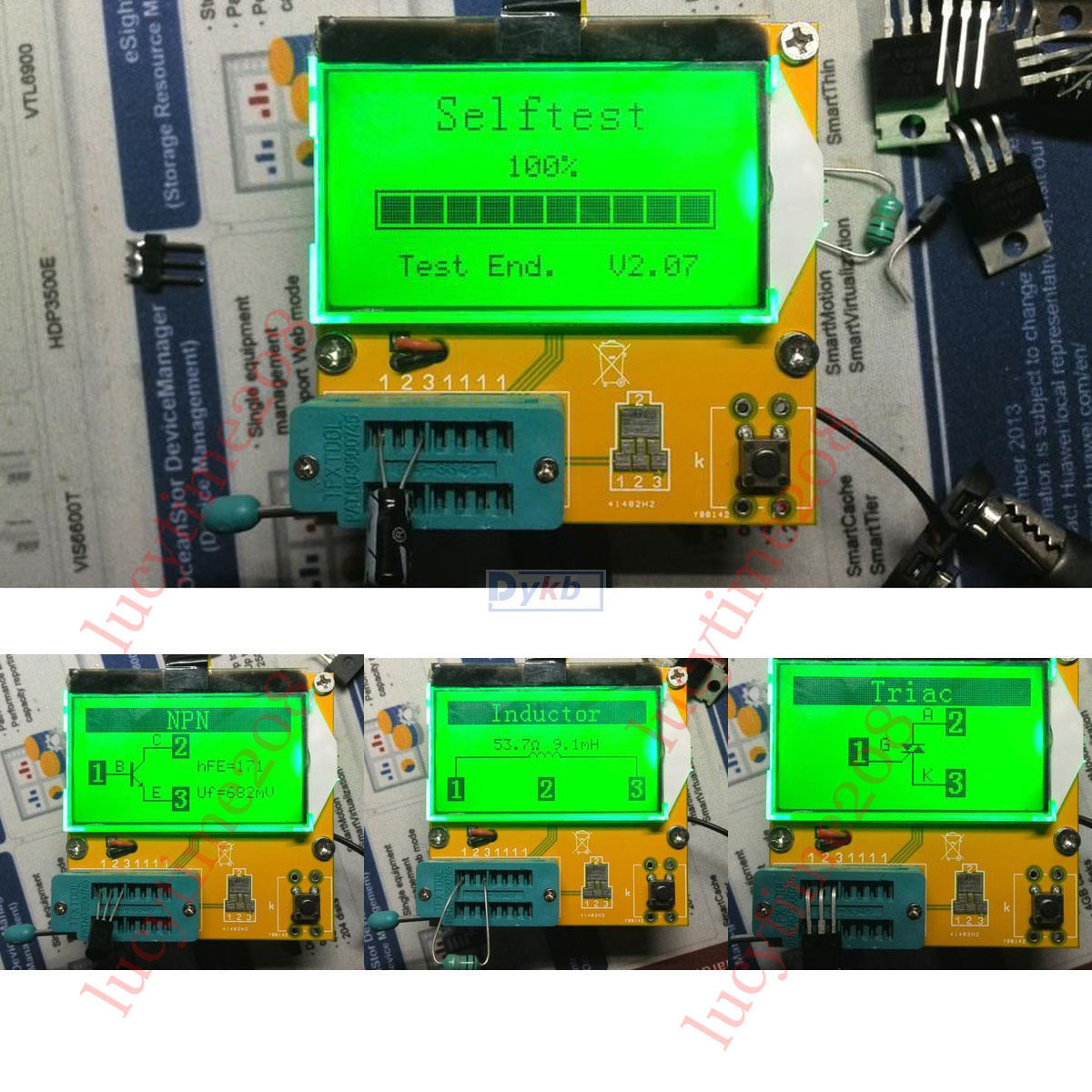
In the meantime, I received a whole bunch of new stuff. The most interesting things are some goldcaps, solar panels, LCR meter, RF24 modules with antenna, partly dead MX510 mouse (as a spare part donor for the mouse I am using for years), and other small stuff. I should do an unboxing video one day :)
I did some experiments with the goldcaps, and I'll put together some more info in upcoming days.
Zobrazují se příspěvky se štítkemArduino Due. Zobrazit všechny příspěvky
Zobrazují se příspěvky se štítkemArduino Due. Zobrazit všechny příspěvky
úterý 17. března 2015

sobota 7. března 2015
Barbie bed

 I used my old good Proxxon table saw. The saw is fastened to a little plank of wood by four screws, and then the plank is fastened to the table with two clamps. To cut big pieces of plywood more or less rectangular, I made a bigger working are of plywood and some squared timber. It's not perfectly rectangular, and has other problems, but with a bit of effort, the results are at least satisfying.
I also made another attempt on the high voltage power supply for GM counter. The results are even worse than the previous attempt, and I am wondering why. I ordered some 9.1MOhm SMD resistors, and next attemp will use SMD transistors, the same I used for the very first supply.
Some minor changes were done to the central node code as well, but nothing major. I started to look into the available libraries for RFM12B that could be used with Due. I found one, using SPI port, but I am a bit skeptical about it - plus, of course, I have no free SPI CS pins. However, I am considering getting rid of the display, and if nothing else, I can just convert an existing library to use SW SPI.
Why removing the display? First, I am not sure how useful it will be in final product. It is pretty useful now, but the nRF24L01 modules have quite short range, and even with 250kbps, the signal doesn't make it through walls to the bathroom. To overcome this, I am considering putting the central node to more central location in the appartment, but then the display will be useless. Second, as clearing the screen takes over 100ms, it would greatly impact the response time of the RF24Network, eventually losing packets randomly, and I don't like that idea.
pondělí 2. března 2015
Arduino Due rant and debouncing
Mostly ranting today. I wonder who came up with the brilliant idea to name Arduino Due this way. Did they realize that 'due' is regular English word, and googling up 'Arduino Due xxx', where xxx is a description of the problem, or a library name, will point to regular Arduino article that accidentally uses the word 'due'?
Yeah, I can use doublequotes, but I usually forget to do that. What will be the next great name? 'Arduino And'? 'Arduino The'? Or even better, 'Arduino Sex'? (Actually, that leads to interesting results in Google already). I am already pissed off with that misplaced connector problem (as I described few days ago), and I am more and more believing that those Italians should stick with what they do best (ice cream and pizza), and for gossake don't mess with electronics! (Just kidding, I still like Arduino).
Anyway. I spent a few hours adding button support, or better said debouncing, and using the button to switch between different screens on the display. I tried to use regular Bounce2 library, but that does not compile, and I didn't want to mess with the library. The easiest solution was to use my old debouncing code that also supports autorepeat. The code isn't mine, I found it years ago, and works like a treat. Just call this piece of code in regular intervals, like 10ms, and tweak the constants according to how often the code is being called.
(I just looked up in my old sources that it's based on algorithm by guy KimmoHop from avrfreaks.org)
I reviewed the CR2032 node and noticed that there's a potential short circuit that might ground the analog input of the battery voltage measurement when wet. I fixed that, and will give it a try overnight. The voltage is 2890mV right now (it has changed a little after I cut the traces that were likely causing the problems, which suggests they actually had some conductance... or not?)
Yeah, I can use doublequotes, but I usually forget to do that. What will be the next great name? 'Arduino And'? 'Arduino The'? Or even better, 'Arduino Sex'? (Actually, that leads to interesting results in Google already). I am already pissed off with that misplaced connector problem (as I described few days ago), and I am more and more believing that those Italians should stick with what they do best (ice cream and pizza), and for gossake don't mess with electronics! (Just kidding, I still like Arduino).
Anyway. I spent a few hours adding button support, or better said debouncing, and using the button to switch between different screens on the display. I tried to use regular Bounce2 library, but that does not compile, and I didn't want to mess with the library. The easiest solution was to use my old debouncing code that also supports autorepeat. The code isn't mine, I found it years ago, and works like a treat. Just call this piece of code in regular intervals, like 10ms, and tweak the constants according to how often the code is being called.
#define DELAY_DEBOUNCE 10
#define DELAY_REPEAT_START 40
#define DELAY_REPEAT 25
void UpdateButtons (void) {GetButtons() returns what buttons are pressed in form of bitmap. Global variable Buttons contains a bitmap of pressed buttons. When you process particular button, clear the corresponding bit in Buttons. The constants above are fine when calling the function every 10ms.
static byte id = 0x00;
static word key_counter = 0;
byte c;
c = GetButtons ();
if (c == 0) { // No key pressed
id = 0;
key_counter = 0;
} else if (c != id) { // New key differs from previous one
id = c;
key_counter = 0;
} else { // New key is the same as previous
key_counter++;
}
if (key_counter == DELAY_DEBOUNCE) { // Debouncing complete
Buttons = id;
} else if (key_counter == DELAY_REPEAT_START) { // Repeated key
Buttons = id;
key_counter -= DELAY_REPEAT;
}
}
(I just looked up in my old sources that it's based on algorithm by guy KimmoHop from avrfreaks.org)
I reviewed the CR2032 node and noticed that there's a potential short circuit that might ground the analog input of the battery voltage measurement when wet. I fixed that, and will give it a try overnight. The voltage is 2890mV right now (it has changed a little after I cut the traces that were likely causing the problems, which suggests they actually had some conductance... or not?)
neděle 1. března 2015
Telling the time
A bit lazy day today, spent on eBay and selling some old junk, getting what was already sold ready for shipment, and playing with the Due central node a little. The node now retrieves the time via NTP and sets its local clock, another step towards telling the time to all nodes that are interested. I did some minor changes of the code, added button and photoresistor to the node, and improved the LED support to make them blink smoothly.
The CR2032 node reported battery dead in the morning. I measured the CR2032 cell and found out that the voltage is perfectly fine. That explains what is going on - it must be the air moisture. Either it condenses on the resistors of the voltage divider, or the cheap chinese paper PCB gets soaked and its resistence decreases. I know it's a really cheap PCB and I am not blaming anyone, I bought a pack of fifty for few euros and they so far performed well. Anyway, I'll leave one of them on balcony for a day and see if it will show any measurable resistence.
If the problem is in the air moisture condensing on the resistors of the voltage divider (they're something like 1M5 and 330K if I recall the values correctly), I'll use standard through-hole resistors for the divider, and maybe smaller values. It should not be a problem, I am grounding the lower end of the divider before measurement, thus it should not draw any noticeable current anyway.
Speaking of power consumption - after the node dried up and the reported voltage stabilised at 2920mV, it didn't change a single bit. Did I finally succeed in creating a sensor node that will run off the CR2032 cell for a few months at least? *evil grin*
The CR2032 node reported battery dead in the morning. I measured the CR2032 cell and found out that the voltage is perfectly fine. That explains what is going on - it must be the air moisture. Either it condenses on the resistors of the voltage divider, or the cheap chinese paper PCB gets soaked and its resistence decreases. I know it's a really cheap PCB and I am not blaming anyone, I bought a pack of fifty for few euros and they so far performed well. Anyway, I'll leave one of them on balcony for a day and see if it will show any measurable resistence.
If the problem is in the air moisture condensing on the resistors of the voltage divider (they're something like 1M5 and 330K if I recall the values correctly), I'll use standard through-hole resistors for the divider, and maybe smaller values. It should not be a problem, I am grounding the lower end of the divider before measurement, thus it should not draw any noticeable current anyway.
Speaking of power consumption - after the node dried up and the reported voltage stabilised at 2920mV, it didn't change a single bit. Did I finally succeed in creating a sensor node that will run off the CR2032 cell for a few months at least? *evil grin*
sobota 28. února 2015
Back from Embedded World 2015!
I did not update the blog for a few days. I was on Embedded World 2015 in Nuremberg, visited customer in Essen, and then recovering from all that :) All that were business trips, and I can tell you that all of that was exhausting. I took train to Essen and back, and that was refreshing, I really enjoyed that... but still, it's five hours on train.
 We spoke to some people on MS booth (not MS directly), and we were given this 16GB USB stick. I originally thought it's a chewing gum or something. The other side says "Internet of Your Things". IoT was a major buzzword this year. Why not.
I also brought a new STM Nucleo board. I don't have it with me, and I don't remember the model number - just guessing it's the F303RE variant. Unfortunately, I didn't realize I could (and should) register for the NFC expansion board.
I did not bring anything from Essen, but we had time to have a lunch in Maredo steakhouse. Yum!
As for the hardware projects, I did a few minor things.
I was about to update the "white" clock with support for buttons to set time, and when looking into the code, I realized I did it already long time ago. It's funny, the clock was sitting on my desk for a few months and waiting for the update.
I received some goodies from China, one of them a boost-buck converter. I hooked it to the solar panels and I can see it works as expected. The panel voltage dropped to something like 2.5V, so it's still far from ideal, but it was pretty cloudy today anyway. The lead accu I ordered almost a month ago still did not arrive, and I can't test the whole setup with it (eBay case opened already).
 I played with the sensor nodes a little, and added some indicator LEDs to the central node, just to show if it's alive, and if packets arrive from time to time. I wanted to use PWM, and most of the PWM capable pins are on that odd-placed Arduino connector (pins 8-13). The trick to make the connector compatible with stripe board can be seen on left. Those are originally pins extracted from right-angled pinheader, and they're bent accordingly using pliers.
 I am also making another attempt with the CR2032 based node. I placed it outside on a dry place, let it report every minute, and I will monitor the battery voltage again. It started with 2.94V - or actually a bit higher, but the voltage dropped after moving the node to the balcony. Outside temperature is around 4°C, compared to something like 22°C inside, thus some voltage drop was expected. Other nodes are scattered around the home, just to keep the central node busy.
Last but not least, I again put some stuff on eBay. I sorted out the vacuum tubes I purchased some weeks ago, and found some that might sold (like DY-802, 25kV diode that could be used for X-Ray). We'll see.
I also brought a new STM Nucleo board. I don't have it with me, and I don't remember the model number - just guessing it's the F303RE variant. Unfortunately, I didn't realize I could (and should) register for the NFC expansion board.
I did not bring anything from Essen, but we had time to have a lunch in Maredo steakhouse. Yum!
As for the hardware projects, I did a few minor things.
I was about to update the "white" clock with support for buttons to set time, and when looking into the code, I realized I did it already long time ago. It's funny, the clock was sitting on my desk for a few months and waiting for the update.
I received some goodies from China, one of them a boost-buck converter. I hooked it to the solar panels and I can see it works as expected. The panel voltage dropped to something like 2.5V, so it's still far from ideal, but it was pretty cloudy today anyway. The lead accu I ordered almost a month ago still did not arrive, and I can't test the whole setup with it (eBay case opened already).
I played with the sensor nodes a little, and added some indicator LEDs to the central node, just to show if it's alive, and if packets arrive from time to time. I wanted to use PWM, and most of the PWM capable pins are on that odd-placed Arduino connector (pins 8-13). The trick to make the connector compatible with stripe board can be seen on left. Those are originally pins extracted from right-angled pinheader, and they're bent accordingly using pliers.Last but not least, I again put some stuff on eBay. I sorted out the vacuum tubes I purchased some weeks ago, and found some that might sold (like DY-802, 25kV diode that could be used for X-Ray). We'll see.
neděle 22. února 2015
Arduino Due Central Node, part III

Another thing that might have caused problems was the DMA mode used for the display. I decided to turn it off in the end, after realizing it doesn't really play well with other devices on the SPI bus. The sources mentioned something like that the DMA can stall other devices. What I noticed was more like the opposite - clearing the screen took 29ms with DMA enabled before other devices were activated, but a few seconds in the main program loop where other devices were talked to!
I changed the sensor node code to be more similar to the sample code I already wrote. Resulting code uses just pure RF24 radio without the RF24Network extension, runs on 250kbps for longer range, and does not use any acks. I might change it in the future after doing some tests. The sensor node also uses EEPROM and simplified identification in form of two characters, like 'T0' for first temperature sensor etc. The packet that temperature sensors send looks like this:
typedef struct PACKED {
uint8_t PacketType;
uint8_t BattLevel;
uint16_t Flags;
uint16_t SensorId;
uint16_t Temperature[2]; // Up to two temperatures in tenths of degrees.
} SensorPayloadTemperature_t;
To recap, I am planning four types of nodes:
- Central node - Arduino Due, has Internet access and serves as a central hub
- Network nodes - support RF24Network (maybe with Mesh extension), typically used for bigger tasks with a lot of communication happening
- Broadcast receivers (consumers) - RF24 radio only, receiving broadcast info from Central node but do not send anything back. Typically clocks etc. Broadcast receivers have no ID
- Sensors - RF24 radio only, sending data to Central node, not receiving anything. Have simple two char ID to distinguish between multiple sensors of one type
Last but not least. After finishing the Friday's entry, I finally had chance to try my new telescope out. It probably needs some adjusting, but I was able to identify that bright planet I was seeing from my window every evening. It's Jupiter, and I can confirm it as I saw its moons - for the first time in my life! It left me in awe, and Jupiter is no more just a word, but something that physically exists for me.
pátek 20. února 2015
Arduino Due Central Node, part II
I spent most of the yesterday evening despairing and tearing my hair, struggling with the RF24 nodes on Arduino Due. The logic analyzer gave me confusing results, the signals did not make any sense, and of course the node didn't respond, no matter how I tried. Well, in fact it did respond when I touched the MISO pin, but that wasn't the kind of response I hoped for. Those strange signals on logic analyzer turned out to be caused by slow sampling, and all worked fine when I bumped the sampling frequency to max (24MHz). Anyway, I gave up and went to bed, as I was tired and could not think straight.
Yes, you guessed that already - I made a mistake when wiring the thing. The RF24 modules have two pins named CE and CSN. I assumed that CE is SPI chip select, and CSN is something specific to RF24 module. Even when I saw that the RF24 does not respond, I still did not realize that the module is obviously not selected and there's something wrong with chip selects. Well, that will teach me a lesson for next time.
After swapping the pins, all started to work just fine. I quickly tried if I can use any pin as chip select for SPI, but that doesn't work. As I am still planning on attaching RFM12B sender, it will obviously need to be modified for software SPI... oh well, at least I can reuse the code from ENC28J60.
The plan is to have two RF24 modules. One will be running with just a basic RF24 radio stack, withouth ACK, on 250kpbs (for biggest range), with fixed packet size, and its own channel. This will be used for sensor reporting to central node, and for central node to broadcast info.
The second RF24 module will use different channel and will run the whole RF24Network stack. I am not sure what I will use it for, but if nothing else, it will multicast similar info packages, and additionally provide some services, like offering nodes to sign up for mode detailed and extended info etc.
The rest of the evening took me beautifying the code, and I'll check it into SVN. I'll change the sample RF24 node code to use just the basic radio... and hopefully it will solve that strange quick battery discharge problem. By the way - I am not sure if the voltage measurement is actually not the main cause of the problems. The node is soldered together on rather cheap paper-based PCB, and the voltage dividers use pretty high value resistors. It could be that the PCB absorbed some water that decreased the PCB resistance and messed up the whole voltage measurement.
Yes, you guessed that already - I made a mistake when wiring the thing. The RF24 modules have two pins named CE and CSN. I assumed that CE is SPI chip select, and CSN is something specific to RF24 module. Even when I saw that the RF24 does not respond, I still did not realize that the module is obviously not selected and there's something wrong with chip selects. Well, that will teach me a lesson for next time.
After swapping the pins, all started to work just fine. I quickly tried if I can use any pin as chip select for SPI, but that doesn't work. As I am still planning on attaching RFM12B sender, it will obviously need to be modified for software SPI... oh well, at least I can reuse the code from ENC28J60.
The plan is to have two RF24 modules. One will be running with just a basic RF24 radio stack, withouth ACK, on 250kpbs (for biggest range), with fixed packet size, and its own channel. This will be used for sensor reporting to central node, and for central node to broadcast info.
The second RF24 module will use different channel and will run the whole RF24Network stack. I am not sure what I will use it for, but if nothing else, it will multicast similar info packages, and additionally provide some services, like offering nodes to sign up for mode detailed and extended info etc.
The rest of the evening took me beautifying the code, and I'll check it into SVN. I'll change the sample RF24 node code to use just the basic radio... and hopefully it will solve that strange quick battery discharge problem. By the way - I am not sure if the voltage measurement is actually not the main cause of the problems. The node is soldered together on rather cheap paper-based PCB, and the voltage dividers use pretty high value resistors. It could be that the PCB absorbed some water that decreased the PCB resistance and messed up the whole voltage measurement.
středa 18. února 2015
Arduino Due Central Node

Anyway, the ILI9341 library for Due works just great, the ENC28J60 network behaves as well, and both work together. I wrote really basic sketch just to test the hardware, called DueCentral. I plan to move all the diagnostic output to TFT as a first step, and make sure that I can get exact time from network. The node also acts as a web server, maybe I could use it somehow? Like a table of all sensors etc...
Of course, when attempting to slap the stripboard on Arduino, I got pissed off again. I definitely need all the connectors to be available on the stripboard, including the famous one that's shifted by 50mils (pins 8-13). This connector provides some pretty important signals, like 10 for SPI CS, and the rest is available as PWM. Oh well, what should I expect from a board designed in Italy - the guys should stick with making ice cream, and don't mess with electronic.
I wanted to update the GM counter sketch yesterday, but I figured out I don't really know what I expect to be displayed and measured, so let's leave it alone for a few days.
pondělí 16. února 2015
ENC28J60 library, GM counter - part III
Lazy evening today, but what would you expect on Monday. I spent most of the time getting the ENC28J60 library to work on Arduino Due, and I succeeded in the end. One of the problems I met was the fact that Due fed from USB cable wasnt' able to provide enough power to the network chip. That was really strange, as the USB cable was connected to a powered hub, but whatever... after using a barrel jack with 12V, the network started to work. I had to do a few minor changes in the library itself, mostly sorting out of the small incompatibilities, like replacing "sei" with "interrupts" etc. The library is available from SVN, revision 154.
I changed the code for GM counter slightly to update the CPM more frequently, basically guessing the CPM based on 5 second measurement with a running average over 30 seconds, and I changed the display from mR/h to uR/h. The natural background shown is between 5-15 uR/h, which is more or less of what I'd expect. According to web, the natural background in Munich is around 0.8mSv/a, that's 80mR/a. Year has 8766 hour, thus we should expect to measure roughly 10uR/h.
I changed the code for GM counter slightly to update the CPM more frequently, basically guessing the CPM based on 5 second measurement with a running average over 30 seconds, and I changed the display from mR/h to uR/h. The natural background shown is between 5-15 uR/h, which is more or less of what I'd expect. According to web, the natural background in Munich is around 0.8mSv/a, that's 80mR/a. Year has 8766 hour, thus we should expect to measure roughly 10uR/h.
sobota 14. února 2015
ENC28J60 library, GM counter

Unfortunately, there are two problems:
- the library I originally got was version for regular Arduinos. It took me some time and research to find out there is a branch numbered 1.5.x that is compatible with Arduino Due and Arduino 1.5.x. In fact, I figured this just as I am writing this text. I originally only got a ZIP file what was linked from forum, and just now I realized it's a branch of the library. Anyway, I had problems to compile the thing, and in the end something went wrong and the library stopped work at all. I suspect Arduino, I was changing the versions of the library, and at one moment I had Arduino actually using a library I already deleted!
- the library seems to have a known bug that the communication hangs after a short while. This was supposedly fixed in the branch I didn't have this morning, so I had no chance to test it, and then I moved to another project.
I was fed up with that, and moved to the GM counter project. I used slightly different HV power supply for this variant, and it wasn't a good idea. The power supply is safer, sort of, because the output voltage bleeds to zero quickly when I remove the battery. The previous power supply kept the output capacitor charged, and despite it's just something like 10nF, those 450V made a nice spark when I shorted it with a screwdriver! The new power supply drops the voltage to zero within a second or so. Another problem with this new one is the power consumption - unloaded, it draws around 5mA from 5V power supply. The old one, with some tweaking, draws less than 500uA. I am considering to change the new power supply to the old one. See this page. The very first one is the "new" one, second is the "old" one. The second is simpler and better, and given the fact I power it from 4.2 LiIon, there's no need to stick with the new design.
I also found out that when it comes to inductance, bigger is better. The guy recommends 10mH, but I am getting the best performance with an inductance so big I even cannot measure it. The second best is my home wound pot core inductor with something like 80mH. Less inductance means bigger power consumption.
I also received some small toroid cores and I tried to wind my own inductor in an attempt to make the 10mH reference one as being used by the "old" HV power supply. I found nice video about winding toroids, and tried it myself. It's a good idea, unfortunately my wire was thinner, and curled all the time. It took me a lot of time to straighten the curls every turn, and in the end some curls bent, and the wire broke after some 30-40 turns out of 100 planned turns. The enamel on the wire was pretty worn out at some spots, and I wouldn't really want to use the resulting coil in a mission critical application. However, with thicker wire, more patience and after finding a way to straighten the wire so it stays so, I can make my own inductors!
The fastest way to high inductances turned out to be a combination of pot core with plastic holder, and an electric drill. In no time, I had a pot core with few hundreds of turns.
pátek 13. února 2015
ENC28J60 library for Due

It did not work, no ping, nothing. I wasn't surprised, as I expected a few packed structure and endianity problems. First thing I wanted was to check if the soft SPI implementation works correctly. I took the Saleae logic analyzer, hooked it to the SPI bus, and captured the communication. All looks fine, the values make sense, and they're same as the values the code actually tries to write to the chip. I was a bit puzzled by the fact the chip does not send any meaningful output, the MISO line stays at the same level all the time. However, after capturing some more, I actually noticed that later on, the chip sends some data via MISO line.
All looks good, but still, there's no ping, no matter what. As a next step, I'll add some code to read something from the chip, preferrably a known value, like stepping or something to make sure that reading also works.
When looking for some details on the web, I found out that the same guy who wrote the UIPEthernet library I am using also wrote the Due port of it. That one still uses the HW SPI, but could help when it comes to those problems when migrating 8bit to 32bit code.
Completely different topic. My telescope arrived yesterday, but so far the sky wasn't clear and I had no chance to test it, hopefully over the weekend. It's a very cheap and basic telescope and I don't expect miracles, but hopefully it will help me to identify the planet I am seeing every evening from my window.
The other thing that arrived yesterday are the fuse holders that I am planning to use as holders for the SBM-20 GM tube. If my wife's computer behaves and won't demand my attention, I could have quite interesting weekend!
čtvrtek 12. února 2015
RasPi or not...
No updates yesterday, sorry. I was looking for the best library I could use for the ILI9341 display from C code on RasPi, and ended up rewriting the Adafruit library. However, the whole thing is object oriented, inheriting stuff from the GFX class that inherits the stuff from Print class... not that it's impossible to port all those to RasPi, but I got bored pretty quickly. I cannot guarantee that it will work, and I don't want to waste one evening by porting a few C++ libraries, then another evening debugging it, and in the end finding out it does not work.
I thought about it and decided to go back to Arduino, abandoning the whole RasPi idea for now. In fact, there's not much of benefit in using RasPi. I was thinking about that email checker, but I still don't know I really want it. If I decide I really do, I can hook up the RasPi to the whole system somehow. The limitations of RasPi do not overcome the benefits. So - I am back to Arduino. I in fact want to use Due this time, making at least one small step towards ARM. Due has enough of RAM, enough of pins, three HW SPI ports, and even DMA.
When looking for a good ILI9341 library, I verified that Adafruit works fine, but there's another library based on Adafruit code that allows using HW SPI, and even DMA, making the display blazingly fast. Library is made by Marek Buriak (?) and can be found here.
There's a few open things related to SPI on Due. The chip supports three HW CS pins, but I might need more. Can I combine hardware and software CS? Or will I need to move some of the peripherals to software SPI? I am planning on using the ILI9341 display, ENC28J60 network, and a few nRF24L01 modules. My guess is that the ENC28J60 library will need porting, and thus using the software SPI would be the easiest way to go.
Anyway, the ILI9341 works, I'll test the RF24 modules tomorrow, and if all looks good, I'll start porting one of the ENC28J60 libraries. There's Ethercard library I am already using for other projects, and then there's arduino_uip that looks good, too. I am also running out of ENC28J60 modules, I actually had to steal one for testing from an older project that's on standby right now.
I thought about it and decided to go back to Arduino, abandoning the whole RasPi idea for now. In fact, there's not much of benefit in using RasPi. I was thinking about that email checker, but I still don't know I really want it. If I decide I really do, I can hook up the RasPi to the whole system somehow. The limitations of RasPi do not overcome the benefits. So - I am back to Arduino. I in fact want to use Due this time, making at least one small step towards ARM. Due has enough of RAM, enough of pins, three HW SPI ports, and even DMA.
When looking for a good ILI9341 library, I verified that Adafruit works fine, but there's another library based on Adafruit code that allows using HW SPI, and even DMA, making the display blazingly fast. Library is made by Marek Buriak (?) and can be found here.
There's a few open things related to SPI on Due. The chip supports three HW CS pins, but I might need more. Can I combine hardware and software CS? Or will I need to move some of the peripherals to software SPI? I am planning on using the ILI9341 display, ENC28J60 network, and a few nRF24L01 modules. My guess is that the ENC28J60 library will need porting, and thus using the software SPI would be the easiest way to go.
Anyway, the ILI9341 works, I'll test the RF24 modules tomorrow, and if all looks good, I'll start porting one of the ENC28J60 libraries. There's Ethercard library I am already using for other projects, and then there's arduino_uip that looks good, too. I am also running out of ENC28J60 modules, I actually had to steal one for testing from an older project that's on standby right now.
Přihlásit se k odběru:
Příspěvky (Atom)